| Modeling/ Using the Numeric Interface for Accurate Modeling |
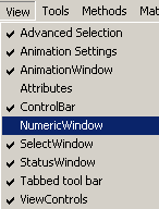
Using the Numeric Interface for Accurate ModelingIntroductionIn addition to the mouse, the input data for creating and transforming objects can also be defined using a numeric interface. For example, to create a curve by entering the control points numerically: 1. Open the numeric window by selecting the pull-down menu 'View/NumericWindow'.
2. Activate the Nurbs Curve tool from the 'NURBS' tab. The numeric window now shows you controls specific to the NURBS Curve tool. There are two fields: 'Position' and 'Relative'. The former allows you to define coordinates in 'world' space. The latter allows you to define points relative to the previously entered point (or to the 'hot point', which is the origin of the input plane, when no points has been entered yet). 'Relative' coordinates can also be accessed in polar (angle coordinate) form. 3. Hit the 'n' key. This activates the 'Position' field. You can also click the field in the numeric window to activate it.
4. Enter three coordinates by separating them with a white space and hit Enter. This creates the first point for the curve.
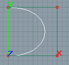
5. Enter three more points. After each entered point click the Enter key. Note: in some countries comma ',' is used as decimal point in which case you can replace the '.' in the following examples with comma. 0.1 0 0 Now four points has been added to the curve, and it has an arc-like shape:
6. Let us try the relative measuring next: hit the 'Tab' key. The 'Relative' field becomes activated. Type the coordinates 0 -0.2 0 and hit Enter. A new point is added -0.2 meters below the first one. The relative measuring field remains active and you can continue entering coordinates this way, or hit 'Tab' until the focus gets back to the 'Position' field. 7. Now click the 'Accept' button in the tool control bar. This terminates the curve tool and the curve is created. Expression evaluationAll numeric fields support standard expression evaluation. For example, to create a sphere with a radius sin(0.3) 1. Activate the sphere tool. 2. Click the left mouse button in the View window to define the center of the sphere. 3. Enter numeric mode by hitting the key 'n'. This automatically activates the 'radius' field in the numeric window. Type sin(0.1) and hit Enter. This creates a sphere whose radius is '0.099833'. Note: Also vector fields support expression evaluation. For example, you can define the center of a sphere by entering three expressions separated by a space: 0.1+0.1 2/3 0.224*0.555 Measuring units and accuracyThe program uses internally the standard SI units. For example, positions and sizes of geometric objects are defined as meters. All numeric fields of the user interface convert internal SI units to desired 'current units'. You can select 'current units' from the 'Options Window'. If you want to work with 'millimeters':
Now all numeric fields that represent distances (positions, lengths, etc.) are shown as 'mm' units. Note: you can change units any time. It has no effect to the scene you are modeling. The user interface only displays properties of objects using the new units.
|
 |
 |

